
Products
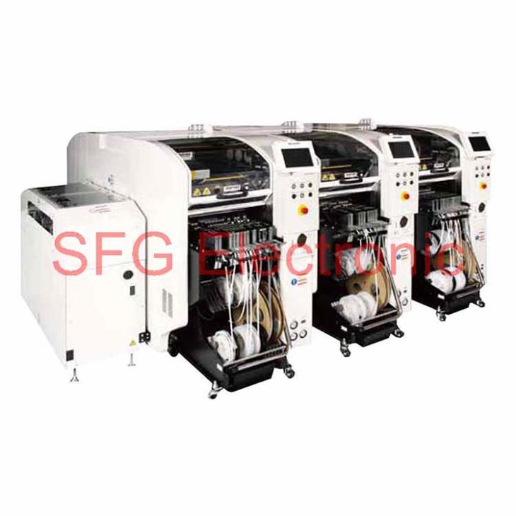
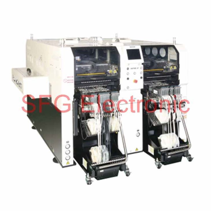
Panasonic SMT Chip Mounter NPM-D3

Feature
High area productivity with total mounting linesHigher productivity and quality with printing, placement and inspection process integration
Configurable modules allow flexible line setupHead location flexibility with plug-and-play functions.
Comprehensive control of lines, floor and factory with system softwareProduction plan support through line operation monitoring.


Total Line solution
Smaller-footprint modular lines by installing inspection heads
Provides high-quality manufacturing with in-line inspection

*1:PCB traverser conveyor to be prepared by customer.*2:Please contact your sales representative for compatible printers and further details.
Multi-Production Line
Mixed production with different type substrates on the same line is also provided with the dual conveyor.

Simultaneous realization of high area productivity and high-accuracy placement
High production mode (High production mode: ON
Max. speed: 84 000 cph *1 (IPC9850(1608):63 300cph *1 )/ Placement accuracy: ±40 μm
High accuracy mode (High production mode:OFF
Max. speed: 76 000 cph *1 / Placement accuracy: ±30 μm(Option:±25μm *2)
*1:Tact for 16NH × 2 head*2:Under conditions specified by Panasonic

New placement head
 |
Lightweight 16-nozzle head |
New high-rigidity base
 |
High rigidity base supporting high-speed / accuracy placement |
Multi-recognition camera

· Three recognition functions combined into one camera
· Faster recognition scan including components height detection
· Upgradable from 2D to 3D specifications
High productivity – Employs dual mounting method
Alternate,Independent & Hybrid Placement
Selectable “Alternate” and “Independent” dual placement method allows you to make good use of each advantage.
• Alternate :
Front and rear heads execute placement on PCBs in front and rear lanes alternately.
• Independent :
Front head executes placement on PCB in front lane and rear head execute placement on rear lane.

High productivity through fully independent placement
Achieved independent placement of tray components by directly linking with NPM-TT (TT2).Capable of fully independent placement of tray components improving cycle time of mid-, large-size component placement with 3-nozzle head. Output of entire line is enhanced.

PCB exchange time reduction
Allow standby PCB with less than L=250mm* at upstream conveyor inside machine to reduce PCB exchange time and improve productivity.
*When selecting short conveyors
Automatic replacement of support pins (option)
Automate position change of support pins to enable non-stop changeover and help save man-power and operation errors.
Quality improvement
Placement height control function
Based on PCB warpage condition data and thickness data of each of the components to be placed, the control of placement height is optimized to improve mounting quality.
Operating rate improvement
Feeder location free
Within same table, feeders can be set anywhere.Alternate allocation as well as setting of new feeders for next production can be done while the machine is in operation.
Feeders will require off-line data input by support station (option).
Solder Inspection (SPI) • Component Inspection (AOI) – Inspection head
Solder Inspection
· Solder appearance inspection

Mounted component Inspection
· Appearance inspection of mounted components

Pre-mounting foreign object*1 inspection
· Pre-mounting foreign object inspection of BGAs
· Foreign object inspection right before sealed case placement

*1: Intended for chip components (except for 03015 mm chip ).
SPI and AOI automatic switching
· Solder and component inspection is switched automatically according to production data.

Unification of inspection and placement data
· Centrally managed component library or coordinate data does not require two data maintenance of each process.

Automatic link to quality information
· Automatically linked quality information of each process assists your defect cause analysis.

Adhesive Dispensing – Dispensing head
Screw-type discharge mechanism
· Panasonic’s NPM has the conventional HDF discharge mechanism, which ensures the high-quality dispensing.

Supports various dot/drawing dispensing patterns
· High accuracy sensor (option) measures local PCB height to calibrate dispensing height, which allows for non-contact dispensing on PCB.

High-quality placement – APC system
Controls variations in PCBs and components, etc. on a line basis to achieve quality production.
APC-FB*1 Feedback to the printing machine
● Based on the analyzed measurement data from solder inspections, it corrects printing positions. (X,Y,θ)

APC-FF*1 Feedforward to the placement machine
· It analyzes solder position measurement data, and corrects component placement positions (X, Y, θ) accordingly.Chip components (0402C/R ~)Package component (QFP, BGA, CSP)

APC-MFB2 Feedforward to AOI /Feedback to the placement machine
· Position inspection on APC offset position
· The system analyzes AOI component position measurement data, corrects placement position (X, Y, θ) , and thereby maintains placement accuracy.Compatible with chip components, lower electrode components and lead components*2

*1 : APC-FB (feedback) /FF (feedforward) : 3D inspection machine of another company can be also connected. (Please ask your local sales representative for details.)*2 : APC-MFB2 (mounter feedback2) : Applicable component types vary from one AOI vendor to another. (Please ask your local sales representative for details.)
Component Verification option – Off-line setup support station
Prevents setup errors during changeover Provides an increase of production efficiency through easy operation
*Wireless scanners and other accessories to be provided by customer

· Preemptively deters component misplacementPrevents misplacement by verifying production data with the barcode information on changeover components.
· Automatic setup data synching functionThe machine itself does the verification, eliminating the need to select separate setup data.
· Interlock functionAny problems or lapses in verification will stop the machine.
· Navigation functionA navigation function to make the verification process more readily understandable.
With the support stations, offline feeder cart setup is possible even outside of the manufacturing floor.
· Two types of Support Stations are available.

Changeover ability – Automatic changeover option
Supporting changeover (production data and rail width adjustment) can minimize time loss

· PCB ID read-in typePCB ID read-in function is selectable from among 3 types of external scanner, head camera or planning form

Changeover ability – Feeder setup navigator option
It is a support tool to navigate efficient setup procedure. The tool factors in the amount of time it takes to perform and complete setup operations when estimating the time required for production and providing the operator with setup instructions.This will visualize and streamline setup operations during setup for a production line.


Operating rate improvement – Parts supply navigator option
A component supply support tool that navigates efficient component supply priorities. It considers the time left until component run-out and efficient path of operator movement to send component supply instructions to each operator. This achieves more efficient component supply.


*PanaCIM is required to have operators in charge of supplying components to multiple production lines.
PCB information communication function
Information of mark recognitions done on first NPM machine in line is passed on to downstream NPM machines.Which can reduce cycle time utilizing the transferred information.


Data Creation System – NPM-DGS (Model No.NM-EJS9A)
This is a software package that provides integrated management of component library and PCB data, as well as production data that maximizes mounting lines with high-performance and optimization algorithms.
*1:A computer must be purchased separately.*2:NPM-DGS has two management functions of floor and line level.

CAD import

Allows you to import CAD data and check polarity, etc., on the screen.
Optimization

Realizes high productivity and also allows you to create common arrays.
PPD editor

Update production data on PC during production to reduce the loss of time.
Component library

Allows unified management of the component library including mounting, inspection and dispensing.
Data Creation System – Offline Camera (option)
Component data can be created offline even while the machine is in operation.
Use the line camera to create component data.Lighting conditions and recognition speed can be confirmed in advance, so it contributes to the improvement of productivity and quality.
 |
Offline Camera Unit |
Data Creation System – DGS Automation (option)
Automated manual routine tasks reduce operation errors and data creation time.
Manual routine tasks can be automated.By collaborating with the customer system, the routine tasks for creating data can be reduced, so it contributes to a significant reduction in production preparation time.It also includes the function to automatically correct the coordinates and angle of the mounting point (Virtual AOI).
Example of entire system image

Automated tasks (excerpt)
·CAD import
·Offset mark setting
·PCB chamfering
·Mounting point misalignment correction
·Job creation
·Optimization
·PPD output
·Download
Data Creation System – Optimization of setup (option)
In production involving multiple models, setup workloads are taken into account and optimized.
For more than one PCB sharing common component placement, multiple setups may be required due to a shortage of suppy units.In order to reduce the required setup workloads in such a case, this option divides PCBs into similar component placement groups, selects a table (s) for setup and thus automates component placement operation.It contributes to improving setup performance and reducing production preparation time for customer manufacturing various kinds of products in small quantities.
Example

Quality improvement – Quality information viewer
This is software designed to support a grasp of changing points and analysis of defect factors through the display of quality-related information (e.g., feeder positions used, recognition offset values and parts data) per PCB or placement point. In case of our inspection head introduced, the defect locations can be displayed in association with quality-related information.


Quality information viewer window
Example of use of quality information viewer
Identifies a feeder used for mounting of defect circuit boards. And if, for example, you have many misalignments after splicing, the defect factors can be assumed to be due to;
1.splicing errors (pitch deviation is revealed by recognition offset values)
2.changes in component shape (wrong reel lots or venders)
So you can take quick action to the misalignment correction.
Specification
| Model ID | NPM-D3 | |||||
|
Rear head Front head |
Lightweight16-nozzle head | 12-nozzle head | 8-nozzle head | 2-nozzle head | Dispensing head | No head |
| Lightweight 16-nozzle head | NM-EJM6D | NM-EJM6D-MD | NM-EJM6D | |||
| 12-nozzle head | ||||||
| 8-nozzle head | ||||||
| 2-nozzle head | ||||||
| Dispensing head | NM-EJM6D-MD | NM-EJM6D-D | ||||
| Inspection head | NM-EJM6D-MA | NM-EJM6D-A | ||||
| No head | NM-EJM6D | NM-EJM6D-D | ||||
| PCB
dimensions*1(mm) |
Dual-lane mode | L 50 x W 50 ~ L 510 x W 300 |
| Single-lanemode | L 50 x W 50 ~ L 510 x W 590 | |
| PCBexchangetime | Dual-lanemode | 0 s* *No 0s when cycle time is 3.6 s or less |
| Single-lanemode | 3.6 s* *When selecting short conveyors | |
| Electric source | 3-phase AC 200, 220, 380, 400, 420, 480 V 2.7 kVA | |
| Pneumatic source *2 | 0.5 MPa, 100 L /min (A.N.R.) | |
| Dimensions *2 (mm) | W 832 x D 2 652 *3 x H 1 444 *4 | |
| Mass | 1 680 kg (Only for main body:This differs depending on the option configuration.) | |
| Placement head | Lightweight 16-nozzle head(Per head) | 12-nozzle head(Per head) | 8-nozzle head(Per head) | 2-nozzle head(Per head) | ||
| High production mode [ON] | High production mode [OFF] | |||||
| Max. speed | 42 000 cph(0.086 s/ chip) | 38 000 cph(0.095 s/ chip) | 34 500 cph(0.104 s/ chip) | 21 500 cph(0.167 s/ chip) | 5 500 cph (0.655 s/ chip)4 250 cph (0.847 s/ QFP) | |
| Placement accuracy (Cpk□1) | ± 40 µm/chip | ±30 μm / chip(±25 μm / chip*5) | ±30 μm / chip | ± 30 µm/chip ± 30 µm/QFP □ 12mm to
□ 32mm ± 50 □ 12mm Underµm/QFP |
± 30 µm/QFP | |
| Component dimensions
(mm) |
0402 chip*6 to L 6 x W 6 x T 3 | 03015*6*7/0402 chip*6 to L 6 x W 6 x T 3 | 0402 chip*6 to L 12 x W 12 x T 6.5 | 0402 chip*6 to L 32 x W 32 x T 12 | 0603 chip to L 100 x W 90 x T 28 | |
| Componentsupply | Taping | Tape : 4 / 8 / 12 / 16 / 24 / 32 / 44 / 56 mm | ||||
| Taping | Max. 68 (4, 8 mm tape, Small reel) | |||||
| Stick | Max.16 (Single stick feeder) | |||||
| Tray | Max.20 (per tray feeder) | |||||
| Dispensing head | Dot dispensing | Draw dispensing |
| Dispensing speed | 0.16 s/dot (Condition : XY=10 mm, Z=less than 4 mm movement, No θ rotation) | 4.25 s/component (Condition: 30 mm x 30 mm corner dispensing)*8 |
| Adhesive position accuracy(Cpk□1) | ± 75 μ m /dot | ± 100 μ m /component |
| Applicable components | 1608 chip to SOP,PLCC,QFP, Connector, BGA, CSP | SOP,PLCC,QFP, Connector, BGA, CSP |
| Inspection head | 2D inspection head (A) | 2D inspection head (B) | |
| Resolution | 18 µm | 9 µm | |
| View size (mm) | 44.4 x 37.2 | 21.1 x 17.6 | |
| Inspectionb processingtime | SolderInspection*9 | 0.35s/ View size | |
| ComponentInspection*9 | 0.5s/ View size | ||
| Inspectionobject | SolderInspection *9 | Chip component : 100 μm x 150 μm or more (0603 mm or more)Package component : φ150 μm or more | Chip component : 80 μm x 120 μm or more (0402 mm or more)Package component : φ120 μm or more |
| ComponentInspection *9 | Square chip (0603 mm or more), SOP, QFP (a pitch of 0.4 mm or more), CSP, BGA, Aluminum electrolysis capacitor, Volume, Trimmer, Coil, Connector*10 | Square chip (0402 mm or more), SOP, QFP (a pitch of 0.3 mm or more), CSP, BGA,Aluminum electrolysis capacitor, Volume, Trimmer, Coil, Connector*10 | |
| Inspectionitems | SolderInspection *9 | Oozing, blur, misalignment, abnormal shape, bridging | |
| ComponentInspection *9 | Missing, shift, flipping, polarity, foreign object inspection *11 | ||
| Inspection position accuracy *12( Cpk□1) | ± 20 μm | ± 10 μm | |
| No. ofinspection | SolderInspection *9 | ||
| ComponentInspection *9 | |||
|
*1 : |
Due to a difference in PCB transfer reference, a direct connection with NPM (NM-EJM9B) / NPM-W (NM-EJM2D) /NPM-W2 (NM-EJM7D) dual lane specs cannot be established. |
|
*2 : |
Only for main body |
|
*3 : |
Dimension D including tray feeder : 2 683 mmDimension D including feeder cart : 2 728 mm |
|
*4 : |
Excluding the monitor, signal tower and ceiling fan cover. |
|
*5 : |
±25 μm placement support option.(Under conditions specified by Panasonic) |
|
*6 : |
The 03015/0402 mm chip requires a specific nozzle/feeder. |
|
*7 : |
Support for 03015 mm chip placement is optional.(Under conditions specified by Panasonic:Placement accuracy ±30 μm / chip ) |
|
*8 : |
A PCB height measurement time of 0.5s is included. |
|
*9 : |
One head cannot handle solder inspection and component inspection at the same time. |
|
*10 : |
Please refer to the specification booklet for details. |
|
*11 : |
Foreign object is available to chip components. (Excluding 03015 mm chip) |
|
*12 : |
This is the solder inspection position accuracy measured by our reference using our glass PCB for plane calibration. It may be affected by sudden change of ambient temperature. |
*Placement tact time, inspection time and accuracy values may differ slightly depending on conditions.
*Please refer to the specification booklet for details.
Hot Tags: panasonic smt chip mounter npm-d3, china,manufacturers, suppliers, wholesale, buy,factory