
Products
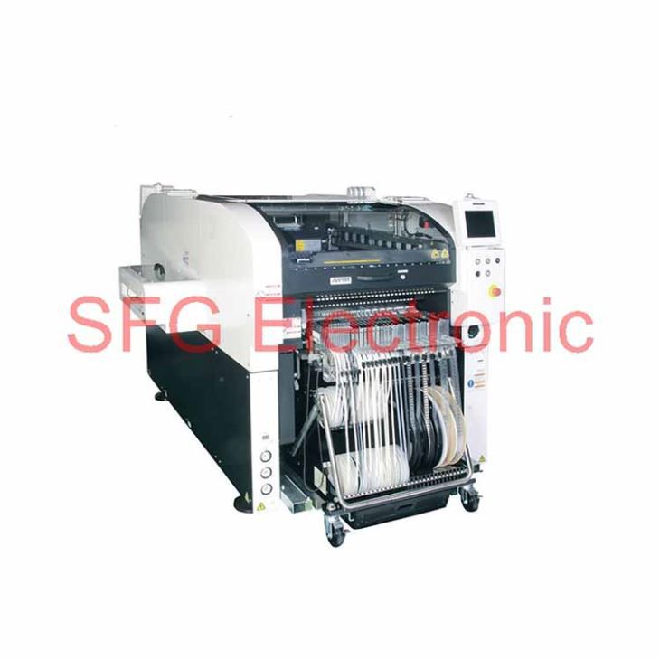
Panasonic SMT Chip Mounter NPM-W2

Features
Higher productivity and quality with printing, placement and inspection process integrationDepending on the PCB you produce, you can select High-speed mode or High-accuracy mode.
For larger boards and larger componentsPCBs up to a size of 750 x 550 mm with component range up to L150 x W25 x T30 mm
Higher area productivity through dual lane placementDepending on the PCB you produce, you can select an optimal placement mode – “Independent” “Alternate” or “Hybrid”

Simultaneous realization of high area productivity and high-accuracy placement
High production mode (High production mode: ON)
Max. speed: 77 000 cph *1 (IPC9850(1608):59 200cph *1 ) / Placement accuracy: ±40 μm
High accuracy mode (High production mode:OFF)
Max. speed: 70 000 cph *1 / Placement accuracy: ±30 μm(Option:±25μm *2)
*1:Tact for 16NH × 2 head*2:Under conditions specified by PSFS

New placement head
 |
Lightweight 16-nozzle head |
New high-rigidity base

· High rigidity base supporting high-speed / accuracy placement
Multi-recognition camera

· Three recognition functions combined into one camera
· Faster recognition scan including components height detection
· Upgradable from 2D to 3D specifications
Machine Configuration
Rear & Front Feeder Layout
 |
60 different components can be mounted from 16mm tape feeders. |
Single Tray Layout

13 fixed feeder slots are available. PoP tray mounting is possible via a transfer unit.
Twin Tray Layout

While one tray is used for production, the other tray can simultaneously be used to setup the next production in advance.
Multi-functionality
Large Board
Single-lane specifications (Selection spec.)

Large Board up to 750 x 550 mm can be handled
Dual-lane specifications (Selection spec.)

Large boards (750 x 260 mm) can be handled collectively.Boards (up to a size of 750 x 510 mm) can be handled collectively during single transfer.
Large Components
Compatible to component sizes up to 150 x 25 mm

LED Placement
Brightness Binning

Avoid mixing of brightness and minimizes component and block disposal.Monitors remaining component count to avoid component exhaust during operation.

*Please ask us for nozzles that support LED components of various shapes
Other functions
· Global bad mark recognition functionReduces in travel/recognition time to recognize bad marks
· PCB standby between machines (with the extension conveyor attached)Minimizes the PCB (750 mm) change time
High productivity – Employs dual mounting method
Alternate,Independent & Hybrid Placement
Selectable “Alternate” and “Independent” dual placement method allows you to make good use of each advantage.
Alternate : Front and rear heads execute placement on PCBs in front and rear lanes alternately.
Independent : Front head executes placement on PCB in front lane and rear head execute placement on rear lane.

Independent changeover
In the independent mode, you can conduct a changeover on one lane while production continues on the other lane.You can exchange the feeder cart during the production also with Independent changeover unit (option). It supports automatic support pin replacement (option) and an automatic changeover (option) so that it provides the best changeover for your production type.

PCB exchange time reduction
Two PCBs can be clamped on one stage (PCB length : 350 mm or less).And Higher productivity can be realized by reducing PCB exchange time.

Automatic replacement of support pins (option)
Automate position change of support pins to enable non-stop changeover and help save man-power and operation errors.
Quality improvement
Placement height control function
Based on PCB warpage condition data and thickness data of each of the components to be placed, the control of placement height is optimized to improve mounting quality.
Operating rate improvement
Feeder location free
Within same table, feeders can be set anywhere.Alternate allocation as well as setting of new feeders for next production can be done while the machine is in operation.
Feeders will require off-line data input by support station (option).
Solder Inspection (SPI) ・Component Inspection (AOI) – Inspection head
Solder Inspection
· Solder appearance inspection

Mounted component Inspection
· Appearance inspection of mounted components

Pre-mounting foreign object*1 inspection
· Pre-mounting foreign object inspection of BGAs
· Foreign object inspection right before sealed case placement

*1: Foreign object is available to chip components.
SPI and AOI automatic switching
· Solder and component inspection is switched automatically according to production data.

Unification of inspection and placement data
· Centrally managed component library or coordinate data does not require two data maintenance of each process.

Automatic link to quality information
· Automatically linked quality information of each process assists your defect cause analysis.

Adhesive Dispensing – Dispensing head
Screw-type discharge mechanism
· Panasonic’s NPM has the conventional HDF discharge mechanism, which ensures the high-quality dispensing.

Supports various dot/drawing dispensing patterns

· High accuracy sensor (option) measures local PCB height to calibrate dispensing height, which allows for non-contact dispensing on PCB.
Self-Alignment Adhesive
Our ADE 400D series is a high-temperature curing SMD adhesive with good component self-alignment effect.This adhesive is also suitable for use in SMT lines to fix bigger components.
After the solder melts, self-alignment and component sinking occurs.


High-quality placement – APC system
Controls variations in PCBs and components, etc. on a line basis to achieve quality production.
APC-FB*1 Feedback to the printing machine
· Based on the analyzed measurement data from solder inspections, it corrects printing positions. (X,Y,θ)

APC-FF*1 Feedforward to the placement machine
· It analyzes solder position measurement data, and corrects component placement positions (X, Y, θ) accordingly.Chip components (0402C/R ~)Package component (QFP, BGA, CSP)

APC-MFB2 Feedforward to AOI /Feedback to the placement machine
· Position inspection on APC offset position
· The system analyzes AOI component position measurement data, corrects placement position (X, Y, θ) , and thereby maintains placement accuracy.Compatible with chip components, lower electrode components and lead components*2

*1 : APC-FB (feedback) /FF (feedforward) : 3D inspection machine of another company can be also connected. (Please ask your local sales representative for details.)*2 : APC-MFB2 (mounter feedback2) : Applicable component types vary from one AOI vendor to another. (Please ask your local sales representative for details.)
Component Verification option – Off-line setup support station
Prevents setup errors during changeover Provides an increase of production efficiency through easy operation

*Wireless scanners and other accessories to be provided by customer
· Preemptively deters component misplacementPrevents misplacement by verifying production data with the barcode information on changeover components.
· Automatic setup data synching functionThe machine itself does the verification, eliminating the need to select separate setup data.
· Interlock functionAny problems or lapses in verification will stop the machine.
· Navigation functionA navigation function to make the verification process more readily understandable.
With the support stations, offline feeder cart setup is possible even outside of the manufacturing floor.
• Two types of Support Stations are available.

Changeover ability – Automatic changeover option
Supporting changeover (production data and rail width adjustment) can minimize time loss

• PCB ID read-in typePCB ID read-in function is selectable from among 3 types of external scanner, head camera or planning form

Changeover ability – Feeder setup navigator option
It is a support tool to navigate efficient setup procedure. The tool factors in the amount of time it takes to perform and complete setup operations when estimating the time required for production and providing the operator with setup instructions.This will visualize and streamline setup operations during setup for a production line.


Operating rate improvement – Parts supply navigator option
A component supply support tool that navigates efficient component supply priorities. It considers the time left until component run-out and efficient path of operator movement to send component supply instructions to each operator. This achieves more efficient component supply.


*PanaCIM is required to have operators in charge of supplying components to multiple production lines.
PCB information communication function
Information of mark recognitions done on first NPM machine in line is passed on to downstream NPM machines.Which can reduce cycle time utilizing the transferred information.


Data Creation System – NPM-DGS (Model No.NM-EJS9A)
The software package helps to achieve high productivity through integral management of creation, editing and simulation of production data and library.
*1:A computer must be purchased separately.*2:NPM-DGS has two management functions of floor and line level.

Multi-CAD import

Almost all CAD data can be retrieved by macro definition registration. Properties, such as polarity, also can be confirmed on screen in advance.
Simulation

Tact simulation can be confirmed on screen in advance so that line total operation ratio can increase.
PPD editor

With quickly and easily compiling placement and inspection head data on the PC display during operation, time loss can be minimized
Component library

A component library of all placement machines including the CM series on floor can be registered to unify data management.
Mix Job Setter (MJS)

Production data optimization allows the NPM-D2 to commonly arrange feeders.Feeder replacement time reduction for changeover can improve productivity
Off-line component data creationoption

With creating off-line component data using a store-bought scanner,productivity and quality can be improved.
Data Creation System – Offline Camera Unit (option)
Minimizes time on machine for parts library programming and assists equipment availability and quality.
Parts library data is generated using the line cameraConditions not possible on a scanner such as Illumination conditions, and recognition speeds, can be checked offline assuring quality enhancements and equipment availability.

Quality improvement – Quality information viewer
This is software designed to support a grasp of changing points and analysis of defect factors through the display of quality-related information (e.g., feeder positions used, recognition offset values and parts data) per PCB or placement point. In case of our inspection head introduced, the defect locations can be displayed in association with quality-related information
 *PC is required for every line.
 Quality information viewer window
Example of use of quality information viewer
Identifies a feeder used for mounting of defect circuit boards. And if, for example, you have many misalignments after splicing, the defect factors can be assumed to be due to;
1.splicing errors (pitch deviation is revealed by recognition offset values)
2.changes in component shape (wrong reel lots or venders)
So you can take quick action to the misalignment correction.
Specification
| Model ID | NPM-W2 | |||||
|
Rear head Front head |
Lightweight16-nozzle head | 12-nozzle head | Lightweight8-nozzle head | 3-nozzle head V2 | Dispensing head | No head |
| Lightweight 16-nozzle head | NM-EJM7D | NM-EJM7D-MD | NM-EJM7D | |||
| 12-nozzle head | NM-EJM7D-MD | |||||
| Lightweight 8-nozzle head | ||||||
| 3-nozzle head V2 | ||||||
| Dispensing head | NM-EJM7D-MD | NM-EJM7D-D | ||||
| Inspection head | NM-EJM7D-MA | NM-EJM7D-A | ||||
| No head | NM-EJM7D | NM-EJM7D-D | ||||
| PCB dimensions(mm) | Single-lane*1 | Batch mounting | L 50 x W 50 ~ L 750 x W 550 |
| 2-positin mounting | L 50 x W 50 ~ L 350 x W 550 | ||
| Dual-lane*1 | Dual transfer (Batch) | L 50 × W 50 ~ L 750 × W 260 | |
| Dual transfer (2-positin) | L 50 × W 50 ~ L 350 × W 260 | ||
| Single transfer (Batch) | L 50 × W 50 ~ L 750 × W 510 | ||
| Single transfer (2-positin) | L 50 × W 50 ~ L 350 × W 510 | ||
| Electric source | 3-phase AC 200, 220, 380, 400, 420, 480 V 2.8 kVA | ||
| Pneumatic source *2 | 0.5 MPa, 200 L /min (A.N.R.) | ||
| Dimensions *2 (mm) | W 1 280*3 × D 2 332 *4 × H 1 444 *5 | ||
| Mass | 2 470 kg (Only for main body : This differs depending on the option configuration.) | ||
| Placement head | Lightweight 16-nozzle head(Per head) | 12-nozzle head(Per head) | Lightweight 8-nozzle head(Per head) | 3-nozzle head V2(Per head) | |||
| High production mode[ON] | High production mode[OFF] | High production mode[ON] | High production mode[OFF] | ||||
| Max. peed | 38 500cph(0.094 s/ chip) | 35 000cph(0.103 s/ chip) | 32 250cph(0.112 s/ chip) | 31 250cph(0.115 s/ chip) | 20 800cph(0.173 s/ chip) | 8 320cph(0.433 s/ chip)6 500cph(0.554 s/ QFP) | |
| Placement accuracy(Cpk□1) | ±40 μm / chip | ±30 μm / chip (±25μm / chip)*6 | ±40 μm / chip | ±30 μm / chip | ± 30 µm/chip± 30 µm/QFP□12mm to □32mm± 50 µm/QFP□12mm Under | ± 30 µm/QFP | |
| Componentdimensions (mm) | 0402*7 chip ~ L 6 x W 6 x T 3 | 03015*7 *8/0402*7 chip ~ L 6 x W 6 x T 3 | 0402*7 chip ~ L 12 x W 12 x T 6.5 | 0402*7 chip ~ L 32 x W 32 x T 12 | 0603 chip to L 150 x W 25 (diagonal152) x T 30 | ||
| Component supply | Taping | Tape : 4 / 8 / 12 / 16 / 24 / 32 / 44 / 56 mm | Tape : 4 to 56 mm | ape : 4 to 56 / 72 / 88 / 104 mm | |||
| Max.120 (Tape: 4, 8 mm) | Front/rear feeder cart specifications : Max.120( Tape width and feeder are subject to the conditions on the left)Single tray specifications : Max.86( Tape width and feeder are subject to the conditions on the left)Twin tray specifications : Max.60( Tape width and feeder are subject to the conditions on the left) | ||||||
| Stick | Front/rear feeder cart specifications :Max.30 (Single stick feeder)Single tray specifications :Max.21 (Single stick feeder)Twin tray specifications :Max.15 (Single stick feeder) | ||||||
| Tray | Single tray specifications : Max.20Twin tray specifications : Max.40 | ||||||
| Dispensing head | Dot dispensing | Draw dispensing |
| Dispensing speed | 0.16 s/dot (Condition : XY=10 mm, Z=less than 4 mm movement, No θ rotation | 4.25 s/component (Condition : 30 mm x 30 mm corner dispensing)*9 |
| Adhesive position accuracy (Cpk□1) | ± 75 μ m /dot | ± 100 μ m /component |
| Applicable components | 1608 chip to SOP,PLCC,QFP, Connector, BGA, CSP | BGA, CSP |
| Inspection head | 2D inspection head (A) | 2D inspection head (B) | |
| Resolution | 18 µm | 9 µm | |
| View size (mm) | 44.4 x 37.2 | 21.1 x 17.6 | |
| Inspection processing time | Solder Inspection *10 | 0.35s/ View size | |
| Component Inspection *10 | 0.5s/ View size | ||
| Inspection object | Solder Inspection *10 | Chip component : 100 μm × 150 μm or more (0603 or more)Package component : φ150 μm or more | Chip component : 80 μm × 120 μm or more (0402 or more)Package component : φ120 μm or more |
| Component Inspection *10 | Square chip (0603 or more), SOP, QFP (a pitch of 0.4mm or more), CSP, BGA, Aluminum electrolysis capacitor, Volume, Trimmer, Coil, Connector*11 | Square chip (0402 or more), SOP, QFP (a pitch of 0.3mm or more), CSP, BGA,Aluminum electrolysis capacitor, Volume, Trimmer, Coil, Connector*11 | |
| Inspection items | Solder Inspection *10 | Oozing, blur, misalignment, abnormal shape, bridging | |
| Component Inspection *10 | Missing, shift, flipping, polarity, foreign object inspection *12 | ||
| Inspection position accuracy *13( Cpk□1) | ± 20 μm | ± 10 μm | |
| No. of inspection | Solder Inspection *10 | Max. 30 000 pcs./machine (No. of components : Max. 10 000 pcs./machine) | |
| Component Inspection *10 | Max. 10 000 pcs./machine | ||
| *1 | : | Please consult us separately should you connect it to NPM-D3/D2/D. It cannot be connected to NPM-TT and NPM. |
| *2 | : | Only for main body |
| *3 | : | 1 880 mm in width if extension conveyors (300 mm) are placed on both sides. |
| *4 | : | Dimension D including tray feeder : 2 570 mmDimension D including feeder cart : 2 465 mm |
| *5 | : | Excluding the monitor, signal tower and ceiling fan cover. |
| *6 | : | ±25 μm placement support option.(Under conditions specified by PSFS) |
| *7 | : | The 03015/0402 chip requires a specific nozzle/feeder. |
| *8 | : | Support for 03015 mm chip placement is optional. (Under conditions specified by PSFS:Placement accuracy ±30 μm / chip) |
| *9 | : | A PCB height measurement time of 0.5s is included. |
| *10 | : | One head cannot handle solder inspection and component inspection at the same time. |
| *11 | : | Please refer to the specification booklet for details. |
| *12 | : | Foreign object is available to chip components.(Excluding 03015 mm chip) |
| *13 | : | This is the solder inspection position accuracy measured by our reference using our glass PCB for plane calibration. It may be affected by sudden change of ambient temperature. |
*Placement tact time,inspection time and accuracy values may differ slightly depending on conditions.
*Please refer to the specification booklet for details.
Hot Tags: panasonic smt chip mounter npm-w2, china,manufacturers, suppliers, wholesale, buy,factory