
Products
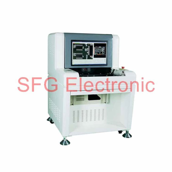
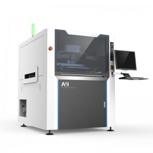
Panasonic SMT Chip Mounter NPM-DX

Panasonic’s next generation of mounting production (X series) concept
“Smart manufacturing”
More line throughput, better quality and lower cost with fully automated mounting system floor
Features
Stable operation based on the autonomic function – Autonomous line controlAPC system and automatic recovery option
Labor-saving, improved utilization – Concentrated controlFloor management system and remote operation option
Reduced work variations – Navigation/automated itemsFeeder setup navigation, component supply navigation and automated items

Increased Productivity/Quality
High-accuracy mode OFF
Max.speed : 184 800cph*IPC9850(1608) : 130 000cph*Placement accuracy : ±25 μm
High-accuracy mode ON
Max.speed : 108 000cph*IPC9850(1608) : 76 000cph*Placement accuracy : ±15 μm
 *Tact for 16NH × 4 head
Improved ability to support components

Standard installation of new functions for better workability (reduced labor needs)

Inclusion of more functions useful to reduce operator’s workload as standard
Instruction of teaching component before starting operation

Extracts components on which automatic teach cannot perform though self-diagnosis at the stat of production and displays the start-up support screen after changeover.
Warning of component exhaust rush occurrence

Predicts simultaneous exhaustion of different components (rush) and notifies the operator of such rush (warning: support request)Normally, displays the length of time before the next component exhaustion takes place on the screen.
Taking the concept and compatibility of NPM series
Data creation, the feeder cart (17-slot) , tape feeder and nozzle are compatible with NPM seriesTaking the concept of NPM series Line connection with NPM-D and NPM-TT series is enabled


*L-sized one is available separately, depending on the component size.
Automatic tape splicing unit
Automates splicing of 8 mm-width tape (paper/embossed).

Taking the concept and compatibility of NPM series

APC system
APC-FB*1Feedback to the printing machine
·Based on the analyzed measurement data from solder inspections, it corrects printing positions. (X,Y,θ)

APC-FF*1Feedforward to the placement machine
·It analyzes solder position measurement data, and corrects component placement positions (X, Y, θ) accordingly.Chip components (0402C/R ~)Package component (QFP, BGA, CSP)

APC-MFB2Feedforward to AOI /Feedback to the placement machine
·Position inspection on APC offset position
·The system analyzes AOI component position measurement data, corrects placement position (X, Y, θ) , and thereby maintains placement accuracy.Compatible with chip components, lower electrode components and lead components*2

*1 : APC-FB (feedback) /FF (feedforward) : 3D inspection machine of another company can be also connected. (Please ask your local sales representative for details.)*2 : APC-MFB2 (mounter feedback2) : Applicable component types vary from one AOI vendor to another. (Please ask your local sales representative for details.)
Automatic recovery option – Pickup position automatic teach in case of an error
When pickup/recognition error occurred, the machine automatically corrects the pickup position without stopping, and resumes production.That improves machine operation rate.(Components: 4 mm embossed (black) / 8 mm paper/embossed (black) tape component. *Embossed tape (transparency) is not supported.)
Automatically resume production after pickup position teach

Automatic recovery option – Re-pickup of error component (retry)
In case of a pickup error, retry pickup without feeding tape. It reduces discard components.
In case of an error: re-pickup (retry) at the current position*No tape feed

No discard component becausetape is not fed.*
□ When re-pickup (retry) is succeeded, the error is not counted□ The number of re-pick (retry) counts can be set.
* : When re-pickup (retry) is succeeded.
Automatic recovery option – Evolved automatic recovery (predicted control)
LNB automatically analyzes the variation of pickup/recognition error rate and instructs the machine to perform teaching to prevent machine error stop.

Remote operation option
Recovery by remote operation is available for the error of which recovery can be made based on human judgment alone.This enables concentrated on-the-floor monitoring, eliminating the time lost for the operator to detect error and take appropriate action, reducing the error recovery time, and thus achieving labor saving and improved operating rate.

Navigation – Feeder setup navigator option
It is a support tool to navigate efficient setup procedure. The tool factors in the amount of time it takes to perform and complete setup operations when estimating the time required for production and providing the operator with setup instructions.This will visualize and streamline setup operations during setup for a production line.
Navigation – Component supply navigator option
A component supply support tool that navigates efficient component supply priorities. It considers the time left until component run-out and efficient path of operator movement to send component supply instructions to each operator. This achieves more efficient component supply.


*PanaCIM is required to have operators in charge of supplying components to multiple production lines.
Placement head maintenance
Good use is made of the machine’s self-diagnosis function to automatically detect the maintenance timing of the placement head. In addition, the maintenance unit can be used to keep the placement head in working condition without requiring skills.
Load checker(Under development)
Measures the“indentation load” imposed by the placement head, and, as the amount of change from the reference value, displays the measured result on the machine’s monitor or LNB.
Head maintenance unit
To automate the inspection and maintenance of the placement head.

Head diagnosis function (Under development)
Inspects the pneumatic circuit condition
Blow error detection *1
Checks the placement blow status
*1:This function comes standard with the machine
Feeder maintenance
Independent of operator skill, the feeder maintenance unit automatically performs feeder performance inspections and calibrations. Its combined use with the PanaCIM maintenance module can automatically prevent the inclusion of non-conforming feeders into production.
Feeder maintenance unit
Automates the inspection of major parts which affect the feeder performance and the calibration of the pickup position.

Thin-type single feeder attachment
Thin-type single feeder attachment*2(option)
*2:The “Thin type single tape feeder” and “Autoload feeder (Under development) “require the “Master jig for thin type single feeder” and “Attachment for thin type single feeder”.
PanaCIM maintenance
Manages the assets of mounting floor, such as machines, heads and feeders, notifies the assets nearing their maintenance dates, and records maintenance histories.
Interlock function
·Monitors the error status during production, and applies Interlock to defective feeders
·Interlock for feeders judged non-conforming by IFMU
Changeover ability – Automatic changeover option
Supporting changeover (production data and rail width adjustment) can minimize time loss

• PCB ID read-in typePCB ID read-in function is selectable from among 3 types of external scanner, head camera or planning form

M2M – iLNB* (Model No.NM-EJS5B)
Collective control of your line composed not only of Panasonic’s machines but of third vendors’ through a single PC provides support for your actual production, quality control and processing.Panasonic is ready to take on the interface between its machines and third vendors’.

|
Item |
Panasonic |
Non-Panasonic |
|
Information collection / display |
○ |
○ |
|
Automatic changeover |
○ |
○ |
*For details, refer to the catalogue or specification for the integrated line management system“iLNB.”
Function list
| Function | Details |
| 1Automatic changeover | 00001.Registration of automatic changeover recipe
00002.Line automatic changeover 00003.Automatic changeover monitoring 00004.Line operation monitoring |
| 2E-Link(Information input) | 00001.Download / edit of schedule |
| 3E-Link(Information output) | 00001.Operation information output
00002.Trace information output 00003.Machine status output |
| 4E-Link(Machine control) | 00001.Machine interlock, Production start control |
| 5E-Link(Feeder write) | 00001.Writing of component data by an external system |
| 6Communicationfunction(GEM・PLC) | 00001.SECS2/GEM communication
00002.OPC communication 00003.IO/RS-232C communication |
*The iLNB comprises software and a computer (iLNB PC).PLC PC, communication conversion PLC, and other devices should be prepared by customers.
M2M – PCB Info Communication FunctionAOI Info Display Option
NPM at the line head recognizes marks, and forwards mark information to downstream NPMs. That eliminates the need for the downstream NPMs to recognize the marks.
Subject for communication
Bad mark recognition

Bad mark is scanned at the first machine.
Pattern mark recognition

All marks are recognized at the first machine and downstream machines only recognize master marks.
*Please refer to“Specificationbooklet” for details.

Information on components judged NG by AOI is displayed both on AOI and NPM.

AOI is used to pinpoint target NPM
The target NPM is put in a warning state, and information from AOI is displayed on the screen
Data Creation System – NPM-DGS (Model No.NM-EJS9A)
This is a software package that provides integrated management of component library and PCB data, as well as production data that maximizes mounting lines with high-performance and optimization algorithms.
*1:A computer must be purchased separately.*2:NPM-DGS has two management functions of floor and line level.

CAD import

Allows you to import CAD data and check polarity, etc., on the screen.
Optimization

Realizes high productivity and also allows you to create common arrays.
PPD editor

Update production data on PC during production to reduce the loss of time.
Component library

Allows unified management of the component library including mounting, inspection and dispensing.
Data Creation System – Offline Camera (option)
Component data can be created offline even while the machine is in operation.
Use the line camera to create component data.Lighting conditions and recognition speed can be confirmed in advance, so it contributes to the improvement of productivity and quality.
 Offline Camera Unit
Data Creation System – DGS Automation (option)
Automated manual routine tasks reduce operation errors and data creation time.
Manual routine tasks can be automated.By collaborating with the customer system, the routine tasks for creating data can be reduced, so it contributes to a significant reduction in production preparation time.It also includes the function to automatically correct the coordinates and angle of the mounting point (Virtual AOI).
Example of entire system image

Automated tasks (excerpt)
·CAD import
·Offset mark setting
·PCB chamfering
·Mounting point misalignment correction
·Job creation
·Optimization
·PPD output
·Download
Data Creation System – Optimization of setup (option)
In production involving multiple models, setup workloads are taken into account and optimized.
For more than one PCB sharing common component placement, multiple setups may be required due to a shortage of suppy units.In order to reduce the required setup workloads in such a case, this option divides PCBs into similar component placement groups, selects a table (s) for setup and thus automates component placement operation.It contributes to improving setup performance and reducing production preparation time for customer manufacturing various kinds of products in small quantities.
Example

Component Verification option – Off-line setup support station
Prevents setup errors during changeoverProvides an increase of production efficiency through easy operation

*Wireless scanners and other accessories to be provided by customer
·Preemptively deters component misplacementPrevents misplacement by verifying production data with the barcode information on changeover components.
·Automatic setup data synching functionThe machine itself does the verification, eliminating the need to select separate setup data.
·Interlock functionAny problems or lapses in verification will stop the machine.
·Navigation functionA navigation function to make the verification process more readily understandable.
With the support stations, offline feeder cart setup is possible even outside of the manufacturing floor.
• Two types of Support Stations are available.
 |
Power Supply Station :Batch Exchange Cart Setup – Provides power to all feeders in cart.Feeder Setup – provides power to individual feeders. |
 |
Component Verification Station :Additional to the power supply station, Component Verification feature is added to this model.The station will navigate you to the location where feeders need exchange. |
Open interface – Host communication option
Able to standardize the interfacing with your systems currently used. Provides data communication with our standard interfaces.

·EventsOutputs a real-time event of equipment
·Other company’s component verificationCommunicates with your component verification systems
·Component management data
·Component remaining quantity data :Outputs component remaining quantity data
·Trace data :Outputs data linked with component information (*1) and PCB information (*2)
(*1) Requires input of component information with a component verification option or an other company’s component verification system I/F(*2) Requires input of PCB information with automatic changeover option
Specification:
| Model ID | NPM-DX | |
| PCB dimensions (mm) *When the long spec. conveyor is selected | Single-lane mode | L 50 × W 50 ~ L 510 × W 590 |
| Dual-lane mode | L 50 × W 50 ~ L 510 × W 300 | |
| PCB exchange time *When the short spec. conveyor is selected | 2.1 s ( L 275 mm or less)4.8 s ( L 275 mm or over to L 460 mm or less) *May differ depending on PCB specifications. | |
| Electric source | 3-phase AC 200, 220, 380, 400, 420, 480 V 5.0 kVA | |
| Pneumatic source *1 | Min.0.5 MPa、200 L /min (A.N.R.) | |
| Dimensions (mm) | W 1 665 *2 × D 2 570 *3 × H 1 444 *4 | |
| Mass | 3 600 kg (Only for main body:This differs depending on the option configuration.) | |
| Placement head | Lightweight16-nozzle head V2(Per head) | Lightweight8-nozzle head(Per head) | 4-nozzle head(Per head) | |
| Max. speed | 46 200 cph(0.078 s/ chip) | 24 000 cph(0.150 s/ chip) | 8 500 cph (0.424 s/ chip)8 000 cph (0.450 s/ QFP) | |
| Placement accuracy (Cpk≧1) | ±25 μm/Square chip | ±25 μm/ Square chip
±40 μm/QFP □12 mm Under±25 μm/QFP □12 mm to □32 mm |
±20 μm/ QFP | |
| Component dimensions (mm) | 0201 component *5*6 / 03015 component *50402 component *5 to L 6 x W 6 x T 3 | 0402 component *5 ~L 45 x W 45 or L 100 x W 40 x T 12 | 0603 chip ~ L 120 x W 90 or L 150 x W 25 x T 30 | |
| Componentsupply | Taping | Tape:4 / 8 / 12 / 16 / 24 / 32 / 44 / 56 mm | Tape:4 ~56 /72 / 88 / 104 mm | |
| Taping | 4, 8 mm tape:Max. 136 | |||
| Stick | Max. 32 (Single stick feeder) | |||
*1: Only for main body
*2: 2 265 mm in width if extension conveyors (300 mm) are placed on both sides.
*3: Dimension D including feeder cart
*4: Excluding the monitor, signal tower and ceiling fan cover.
*5: 0201/03015/0402 component requires a specific nozzle/tape feeder.
*6: 0201 component placement is optional. (Under conditions specified by Panasonic)
* Placement tact time and accuracy values may differ slightly depending on conditions.
* Please refer to the specification booklet for details.
Hot Tags: panasonic smt chip mounter npm-dx, china,manufacturers, suppliers, wholesale, buy,factory